Fig. 1. A pseudo-differential link (PDL).
In 2007, Excem introduced a pseudo-differential signaling scheme providing a reduction of external crosstalk and echo. This section introduces this signaling scheme, which is referred to as ZXnoise method.
A conventional pseudo-differential link (PDL) providing m channels uses an interconnection having n = m transmission conductors (TCs) and a common conductor (CC) distinct from the reference conductor (ground). The PDL is intended to provide low external crosstalk, using fewer conductors than m differential links. A PDL is shown in Fig. 1, this link comprising an interconnection having n = 4 TCs. The transmitting circuit (TX circuit) receives at its input the signals of the 4 channels of the source, and the receiving circuit (RX circuit) outputs the signals of the 4 channels to the user. In a conventional PDL, if a termination circuit (the block containing the resistor symbol in Fig. 1) is used to reduce reflections and thereby increase the bandwidth, it is typically made of grounded resistors. Such a termination circuit degrades the desired protection against external crosstalk.
The Fig. 1 also applies to a PDL implementing the ZXnoise method. Such a PDL providing m channels in a known frequency band uses an interconnection having n = m TCs and a return conductor (RC) distinct from the reference conductor. The designer proportions the interconnection such that it may, in a part of the known frequency band used for transmission, be modeled with a sufficient accuracy as a (n + 1)-conductor multiconductor transmission line (MTL) such that the (n + 1)-conductor MTL uses the natural voltages referenced to the RC and the natural currents as variables, and such that the (n + 1)-conductor MTL has uniform electrical characteristics over its length. The meaning and implications of this requirement are covered in the papers B71 and B73.
This requirement implies that all conductors other than the conductors of the interconnection may be neglected when one models propagation in the interconnection and that, in particular, the reference conductor may be neglected when one models propagation in the interconnection. For instance, the two structures shown in Fig. 2A are appropriate to obtain this result. In both structures shown in Fig. 2A, 1 to 4 are the TCs, 5 is the RC in the coplanar-strips-over-return-conductor structure (a) and the RC is made of the conductors 5A and 5B in the coplanar-strips-inside-return-conductor structure (b). In such structures, the RC in a way acts as an electromagnetic screen which shields the TCs from ground.
However, other interconnection-ground structures utilizing a reduced number of metallization layers are also appropriate to implement the ZXnoise method. For instance, the two structures shown in Fig. 2B may be proportioned to obtain suitable characteristics. In both structures shown in Fig. 2B, 1 to 4 are the TCs, while the RC is made of the conductors 5A to 5E.
As shown in Fig. 1, the ZXnoise method uses at least one termination circuit, each termination circuit being floating and approximately characterized by an impedance matrix with respect to the RC. This impedance matrix is of size n × n, and proportioned using the characteristic impedance matrix of the interconnection with respect to the RC. This part of the design of a ZXnoise PDL is explained in the papers B71, B73, B78 and B81. Also, in the ZXnoise method, the RC is used as a return path for the currents corresponding to the signals. In a conventional PDL, the function of the CC is quite different, hence the different designations.
This short presentation of the ZXnoise method skips many important practical aspects which are explained in the patent applications. For instance, some implementations may use multiple conventional single-ended line drivers as a TX circuit. Other implementations, for instance for full duplex communication (i.e. simultaneous bidirectional transmission), may take advantage of TX circuits producing no common-mode current in the interconnection. The schematic diagram of such a TX circuit is shown in Fig. 3 where 3 input signals are applied to the terminals IN1, IN2 and IN3 respectively, where the 3 TCs are connected to the terminals ST1, ST2 and ST3 respectively and where the RC is connected to the terminal CT. Explanations on such TX circuits are provided in the papers B74 and B75.
The ZXnoise method is a pseudo-differential transmission scheme which provides low reflections. It also provides a good protection against external crosstalk, because the termination circuit is floating with respect to ground and because of the shielding action of the RC. The interconnection may be formed in a rigid or flexible printed circuit board, in the substrate of a multi-chip module (MCM) or hybrid circuit or inside a monolithic integrated circuit. The ZXnoise method seems particularly relevant to system on chip (SoC) and system in package (SiP), where current interconnection technology will not be able to serve the requirements (performances, footprint, cost) of next advanced systems.
The published papers and some of the Patent Cooperation Treaty (PCT) applications related to the ZXnoise method can be reached in the Club Excem section of this web site. The applications P35, P36, P37, P38 were filed in 2007. Note that, in 2008, Excem filed 6 additional patent applications related to electrical interconnections. Four additional patent applications were filed in 2009. Some of these inventions combine the ZXnoise technique (for reducing external crosstalk and echo) and the ZXtalk technique described in Section 3 below (for removing internal crosstalk and residual echo).
The most important step in the optimal use of multipair cables is the creation of appropriate models for the transmission medium. Excem has created an apparatus for the characterization of multipair cables such as cat. 3 and cat. 5 cables, and a method for the probabilistic assessment of crosstalk in various configurations.
Models for the computation of propagation distortion and crosstalk in multipair cables have been introduced a long time ago. The typical model used by the telecom industry for crosstalk predictions involves only two pairs, considered as two circuits. Regardless of the actual number of pairs in the cable, this "two-circuit model" has four independent variables: two differential-mode voltages and two differential-mode currents.
On the other hand, the EMC community has developed the multiconductor transmission line (MTL) theory, for dealing with problems relating to crosstalk, the emission of radiated fields, or the pick-up of external fields, when said problems involve an interconnection having an arbitrary number of conductors. In principle, the MTL theory can be used in problems involving a UTP cable or STP cable with p pairs, plus a reference conductor. Such cables will respectively have n = 2p conductors in the case of the UTP cable, or n = 2p + 1 conductors in the case of the STP cable. The MTL theory is based on matrix equations and is more involved than the two-circuit model, because it implements 2n independent variables. It requires that the cable be characterized with 4 square matrices of order n: a per-unit-length (p.u.l.) inductance matrix, a p.u.l. resistance matrix, a p.u.l. capacitance matrix and a p.u.l. conductance matrix. The MTL theory is of course more accurate than the two-circuit model. In fact, the two-circuit model can be derived from the MTL theory, with ad hoc assumptions.
|
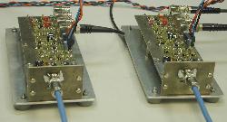
We have explained in B45, B67 and in the SpiceLine User's guide that, if one wishes to apply the MTL theory to multipair cables, it is desirable to implement a change of variables on the voltages and currents, in such a way that the following independent variables are used: p differential-mode voltages, p differential-mode currents, 1 common-mode voltage, 1 common mode current, n − p − 1 other well chosen voltages, and n − p − 1 other well chosen currents. The cable is then characterized by four "symmetry-transformed" matrices of order n, of course related to the ones previously mentionned. Our apparatus, the validation prototype of which is shown on the right, is capable of performing the direct measurement of the symmetry-transformed matrices. |
 |
This necessary step for the implementation of the MTL theory to multipair cables is however not sufficient to obtain accurate crosstalk predictions, since the crosstalk properties of a well-balanced multipair cable are primarily governed by the fluctuations of its electrical characteristics over its length. Using appropriate computational methods, it is possible to derive the "expectation of the square of the modulus of the coupling factor" (ESMCF), both for the near-end crosstalk (NEXT) and for the far-end crosstalk (FEXT), as explained in B55 and B67. The statistical parameters describing the fluctuations of the symmetry-transformed matrices in the corresponding formula can also be measured with our apparatus.
Our published papers and patent on multipair cables can be reached in the Club Excem section of this web site. Companies interested in the possibility of implementing our results should contact us.
|
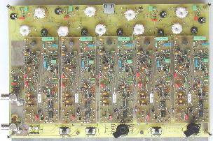
The ZXtalk technology provides a dramatic reduction of echo and internal crosstalk in multiconductor interconnections. It is applicable to the transmission in media such as multiconductor cables (for instance cables of local area networks), traces of printed circuit boards and flex circuits, and on-chip interconnects in integrated circuits. The picture on the right shows validation prototypes which were used to compare actual performances with theoretical predictions. |
 |
We describe below the basics of this new technique, which in theory allows to cancel internal crosstalk, as explained in B54, B56, B58 and B60. In practice, it provides an impressive reduction of crosstalk. This technique is implemented on the example of Fig. 4. It is applicable to any interconnection with n transmission conductors which may be modeled as a uniform multiconductor transmission line (MTL) with a sufficient accuracy. This technique is mainly characterized by the following points:
In the special case of Fig. 4, we have a data bus architecture intended for bidirectional transmission, and the signals needed to control the active state of at most one transmitting circuit at a given time are not shown. We also note that the transmitting circuits and the receiving circuits being connected in parallel to the interconnection, they must present a high impedance to the interconnection, in order not to disturb the propagation of waves and not to produce undesirable reflections at the ends. Using the concept of modal voltages and modal currents as defined in B56 and B58, one may show that the signals of the four channels of a source connected to an active transmitting circuit are sent to the four channels of the destinations, without noticeable crosstalk. There are many possible implementations for this technique, which may use analog circuits and/or digital circuits.
The Fig. 5 shows a schematic for the simulation of a theoretical example of a 30 cm long interconnection with three transmission conductors. This interconnection is intended for unidirectional transmissions. Only one end of the interconnection is connected to a termination circuit made of six resistors R401 to R406, their values being determined in such a way that the impedance matrix of the termination is close to the characteristic impedance matrix. The transmitting circuit comprises three voltage controlled voltage sources E511, E512 and E513, and 10 resistors R521 to R530. This transmitting circuit receives at its input the signal of the three channels of the source represented by the voltage sources V21, V22 and V23. The receiving circuit comprises three voltage controlled voltage sources E611, E612 and E613 and seven resistors R621 to R627. With a suitable choice of part values, crosstalk completely disappears in simulation (performed using SpiceLine and a SPICE program).
Experimental work shows that the ZXtalk technique works as expected. The actual reduction of crosstalk depends on the type and length of the interconnection, on the bandwidth, and on the specific implementation. It is therefore difficult to provide a rule of thumb for the achievable performances. Our results nevertheless imply that this technology could be implemented with on-chip interconnects, PCB traces, and cable based interconnections, for the purpose of using denser (hence cheaper) interconnections, or longer interconnections, or a wider bandwidth.
A variation referred to as "special ZXtalk method for completely degenerate interconnections" uses an interconnection in which all propagation modes have practically the same propagation velocity. The advantage of this requirement is that linear combinations of signals may be avoided in the transmitting circuits and/or in the receiving circuits. Such a simpler implementation may be used to obtain a wider bandwidth.
The eight published papers and the five Patent Cooperation Treaty (PCT) applications related to the ZXtalk can be reached in the Club Excem section of this web site. The 3 initial ZXtalk patents (P26, P27 and P28) have been sold in 2005 to Rambus (Rambus is a U.S. technology licensing company specializing in the invention and design of high speed chip interfaces) and in 2006 to a second U.S. company.
Two subsequent patents applications related to the ZXtalk method are P30 and P33 which define a series-series feedback multiple-input and multiple-output amplifier (MIMO-SSFA). This MIMO-SSFA is an excellent device for the implementation of the special ZXtalk method for completely degenerate interconnections described in P28, because it may provide adequate linear combinations of signals at multi-gigahertz frequencies. Note that the inventions P30 and P33 may also be applied to our MIMOmatch front-end for wireless receivers using multiple antennas.
4. Signal integrity seminarsOur one-day Seminar 32 is derived from the much more comprehensive Seminar 33 described below. The slideshow of the Seminar 32 is available for free download in electronic format or as a low-cost book. It can be used as a synopsis on multiconductor transmission line (MTL) theory and its application to mitigating echo and crosstalk. It might also help you to decide if you want to attend the Seminar 32 or the Seminar 33. See the description of Seminar 32. Our Seminar 33 introduces expert-level approaches for signal integrity in printed circuit assemblies and multi-chip modules (MCMs). It provides detailed propagation models based on the theory of MTLs. This framework is used to describe and analyze most known techniques for reducing crosstalk and echo in multiconductor interconnections, including the ZXtalk technique and the ZXnoise technique. See the description of Seminar 33. This 3-day intensive course is intended for R&D and signal integrity engineers and researchers concerned by the reduction of echo and crosstalk in dense interconnections for wide-band signals. We assume that the participants are familiar with basic signal integrity concepts and results. Our Seminar 32 and Seminar 33 are taught exclusively by Dr. Frédéric Broydé, Senior Member of the IEEE, who authored or co-authored many papers on signal integrity and co-invented a good number of innovative ideas in this area (see Section 5 below). To inquire about the next venues and dates, please send an e-mail to info@eurexcem.com using "Seminar" in the subject line. |
 |
Excem's research engineers have done a lot of R&D on signal integrity and the EMC of interconnections, namely on problems such as the reduction of echo and crosstalk, the emission of electromagnetic power and the pick-up of external fields by wiring.
During the period from January 1989 to May 2010, the results of this activity are:
| URL: http://www.eurexcem.com/copper.htm | © Excem 2003, 2016 |
| Last update: December 22, 2016 | reply to: webmaster@eurexcem.com |